


 Business License

What Are CNC Turning Parts? Lathe Types and Turned Features
A stepped shaft came off the lathe within 0.01 mm on every diameter and failed assembly because the middle section carried 0.04 mm of deflection. The part was 220 mm long with a 12 mm waist, turned in one pass with no steady rest, and the tool simply pushed the work away from itself in the middle.
Turning looks like the simpler of the two machining routes, and for a part under four times its diameter that holds. Push the length, thin the wall or tighten the tolerance and the process starts answering back. The notes below cover the machine types, the features a lathe makes well and the points where a turning quote becomes a different conversation.
1. What CNC Turning Parts Are and How They Are Made
CNC turning parts are rotational components produced by rotating the workpiece against a single-point tool. The tool moves in two axes on a basic lathe, so the geometry it creates is a surface of revolution: diameters, faces, tapers, grooves and threads.
Anything off-axis comes from live tooling or a second operation. A cross hole, a milled flat or a slot on a turned part is done by a driven tool in the turret, or by moving the part to a machining centre.
The economics follow from that geometry. A turned part is cheap per piece because the cut is continuous and the chip load is high, and the setup is short because the workholding is a collet or a chuck rather than a fixture.
Most CNC turning parts basics come down to one idea: the process is fast and repeatable on axis, and everything that leaves the axis costs money.
2. Lathe Types Behind Turned Shaft Components
At Ningbo Changfeng Mechanical Factory four machine types cover most turned shaft components, and the choice is driven by size, volume and how much off-axis work the part needs.
A two-axis lathe with a bar feeder is the workhorse for parts under 42 mm diameter. It runs unattended, holds plus or minus 0.02 mm without effort and produces a part every 30 to 120 seconds depending on feature count.
A Swiss-type lathe slides the bar through a guide bushing, so the tool always works close to the support. That is what allows a 3 mm diameter, 60 mm long pin to be turned without deflection, and it is the reason Swiss machines dominate small precision work.
A turn-mill centre adds a driven tool turret and often a second spindle, which lets a part be completed in one setup with milling and cross drilling included. Multi-spindle machines take the same logic further for high volume, cutting several parts at once from bar.
| Machine | Typical bar range | Typical fit | Cycle character |
|---|---|---|---|
| Two-axis lathe with bar feed | 6 to 42 mm | General turned parts, moderate volume | Fast, minimal handling |
| Swiss-type lathe | 1 to 32 mm | Long slender parts, tight tolerance | Slower per feature, no deflection |
| Turn-mill centre | 20 to 80 mm | Parts with cross holes and flats | One setup, no second operation |
| Multi-spindle | 6 to 40 mm | High volume simple parts | Several parts per cycle |
3. Lathe Turned Features: Grooves, Chamfers, Threads and Bores
The feature list a lathe handles well is long, and knowing it prevents a design that has to move to a mill. External and internal diameters, faces, chamfers, radii, grooves, reliefs, tapers and threads all belong to the turning process.
Threads are the feature buyers ask about most. A turned thread is cut with a single-point tool or a die head, and its quality depends on the tool path rather than on the operator. Class 6g external and 6H internal threads are routine, and holding them requires the thread to be gauged rather than measured. Threads sit among the lathe turned features that most often need a gauge rather than a caliper.
Lathe turned features that cause trouble are the ones near the workholding. A groove or an undercut within 3 mm of the collet face is difficult because the tool has to reach past the jaws without touching them, and a part designed that way pays for it in cycle time.
Deep bores are the other limit. A bore deeper than four times its diameter needs a stepped drilling sequence or a boring bar with a reduced shank, and the finish deteriorates as the bar extends. Beyond six times diameter, the process moves to gun drilling.
4. CNC Turning Parts Basics: Chuck, Collet and Between Centres
Workholding decides the tolerance before the tool does. A three-jaw chuck repeats to about 0.02 mm, a collet to 0.005 to 0.01 mm, and between centres to better than either on a long part.
Collets are the default for bar work because they grip on a ground surface and close uniformly. Their limitation is the range: each collet covers a narrow band, so a shop running many diameters keeps a cabinet of them.
Between-centres work solves the deflection problem on long shafts. The part is held on two centres and driven by a dog, so the cutting force is carried by the centres rather than by the workholding, and a 300 mm shaft can be turned straight.
Those three choices are the practical content of CNC turning parts basics. When a drawing asks for 0.01 mm runout on a long part, the answer is usually centres or a steady rest, not a better insert.
5. Turned Shaft Components: Length to Diameter and Deflection
Deflection is the largest single error source in CNC turning parts basics. It scales with the cube of the unsupported length and inversely with the fourth power of diameter, which is why a small change in length matters more than a small change in tolerance.
A 12 mm diameter shaft unsupported over 220 mm deflects under a normal finishing load by roughly 0.03 to 0.05 mm at the midpoint. No amount of tool care removes that, because the work moves away from the tool and the cut becomes a spring pass.
The remedies are geometric rather than metallurgical. A steady rest placed at the midpoint halves the effective span and cuts deflection by roughly a factor of eight. Turning in two operations, with the part flipped and re-chucked, removes the long unsupported section entirely.
Turned shaft components longer than four times their diameter should be evaluated for support at the quotation stage. A shop that quotes a 220 mm shaft without asking about support is quoting a part it has not planned to make straight.
6. Lathe Turned Features That Cost Extra
Some lathe turned features add cost out of proportion to their size, and they are worth identifying before a drawing is released. The usual candidates are a tight tolerance on a long bore, a thread close to a shoulder, a fine surface finish on an internal face and any feature needing a second setup.
At Changfeng Mechanical a thread that runs to within 1 mm of a shoulder cannot be cut with a standard die head, so it needs a single-point thread with a relief groove. That relief groove has to be on the drawing, because the shop will otherwise cut the thread as far as the tool reaches and the mating part will not seat.
Internal grooves and face grooves cost more than external ones because the boring bar is weaker and the chip has nowhere to go. A face groove 2 mm wide and 4 mm deep on a 25 mm bore is a slow operation, and the chip tends to pack.
Finish is the quiet cost. Requiring Ra 0.4 on a turned surface usually means a wiper insert or a second pass at reduced feed, which adds 10 to 20 percent to the cycle. Requiring the same finish on an internal bore is harder still, because the boring bar deflects and the surface inherits the vibration.
7. A Dowel Pin Case: 0.008 mm on a 60 mm Shaft
A customer needed locating dowels, 8 mm diameter and 60 mm long, held to plus or minus 0.008 mm with 0.01 mm straightness. Turning was the obvious route and the tolerance was inside what a Swiss lathe holds.
The first lot measured well on diameter and failed on straightness, with 0.02 mm of bow across the length. The part was at the edge of the guide bushing range and the bar itself carried 0.03 mm of bend over the 3 metre length, which transferred into the finished part.
The fix was two changes: a straightened bar grade with a straightness call under 0.01 mm per metre, and a centreless grind after turning to correct what the bar brought in. Cycle time rose about 25 percent including the grinding step, and the lot passed on straightness at the first attempt.
At Changfeng Mechanical we now ask for the bar straightness certificate on any turned part with a length to diameter ratio above five, because the material and the process each contribute about half the error, which is the practical limit of turned shaft components at this length to diameter ratio.
8. Bar Feed, Cycle Time and Turned Shaft Components
A bar feeder changes the cost structure of a turning job more than any other single decision. Removing manual loading takes the handling time out of the cycle and lets the machine run through a shift.
The trade-off is the remnant. A 3 metre bar leaves 100 to 200 mm unusable at the end, so a part 220 mm long wastes roughly one part per bar. On a 500 piece order that is a rounding error, and on a 30 piece order it is visible.
Cycle time itself is predictable, which is one of the quieter advantages in CNC turning parts basics. A 25 mm shaft with four turned features and one thread runs roughly 70 to 110 seconds on a two-axis lathe at moderate speed, and the same part on a Swiss machine takes longer per feature because the depth of cut is limited by the guide bushing.
Volume decides which machine runs the work. Below a few hundred pieces, the two-axis lathe with a short setup is cheaper despite the slower cycle, and above several thousand the multi-spindle machine wins on cost per piece.
9. Inspection of CNC Turning Parts Basics on the Floor
Turning inspection is quick because the features are rotational. A micrometer on each diameter, a thread gauge on each thread and a comparator or optical system on the profile covers most parts in under a minute.
Runout needs a different setup: the part between centres or in a V-block, with a dial indicator, rotated through a full revolution. A micrometer cannot detect runout, which is why a lot can measure perfectly on diameter and still fail assembly.
The instrument that catches the most problems is the comparator, because it shows the whole profile against an overlay at once. A chamfer that is 0.2 mm short or a radius that has become a sharp corner shows up immediately, where a dimensional check would pass it.
At Changfeng Mechanical Factory the turning cell gauges every diameter with a micrometer at fixed intervals through the run, and records the readings against the piece count so a drift is visible before a dimension leaves tolerance.
10. Frequently Asked Questions on Lathe Turned Features and Turning Basics
10.1 What length to diameter ratio needs a steady rest?
Above roughly four to one, the deflection becomes visible on a finishing pass, and above six to one it becomes the dominant error. A 12 mm shaft unsupported over 220 mm is at eighteen to one, which is well past the point where a single pass can hold tolerance. A steady rest at the midpoint brings the effective ratio down to nine, and two rests bring it lower still, while where a rest cannot be used because of the geometry the alternative is turning in stages with the part re-chucked, which trades handling time for straightness.
10.2 Can a lathe cut a cross hole without a mill?
Yes, with live tooling. A turn-mill centre carries driven tools in the turret, so a cross hole, a flat or a slot can be cut without moving the part to a second machine. The alternative is a lathe with a bolt-on driven tool holder, which works for light cuts. What a lathe cannot do economically is a feature requiring three axes of simultaneous motion, such as a contoured pocket on a curved surface, and that belongs on a machining centre, while keeping a part on one machine removes the re-fixture error that on a cross hole is often the largest single error in the part.
10.3 Why does a turned diameter drift during a long run?
Tool wear and thermal growth, in that order. A carbide insert wears on the flank through a run, which pushes the diameter slightly larger as the edge loses sharpness, and the spindle and ballscrews warm up over the first hour of production. A run that starts within 0.005 mm of nominal and drifts 0.015 mm by piece 400 is showing both effects. Tool offset compensation at fixed intervals handles the wear, and letting the machine idle to temperature before the first cut handles the rest.
10.4 What surface finish can turning achieve without grinding?
Ra 1.6 is routine on a turned diameter with a normal finishing pass, and Ra 0.8 is achievable with a wiper insert or a reduced feed. Ra 0.4 is possible on external diameters with a sharp tool, high speed and a rigid setup, but it is at the limit and it scatters. Internal bores finish worse than external diameters because the bar deflects, so a bore specified at Ra 0.8 needs a boring bar sized for the depth rather than the largest one that fits the hole.
Recently Posted
-
What Are Industrial Castings? Heavy Duty and Precision Classes
November 18, 2026Two castings sat on the same inspection bench: a 900 kg counterweight frame for a press, and a 12 g insert for a pump shaft. Both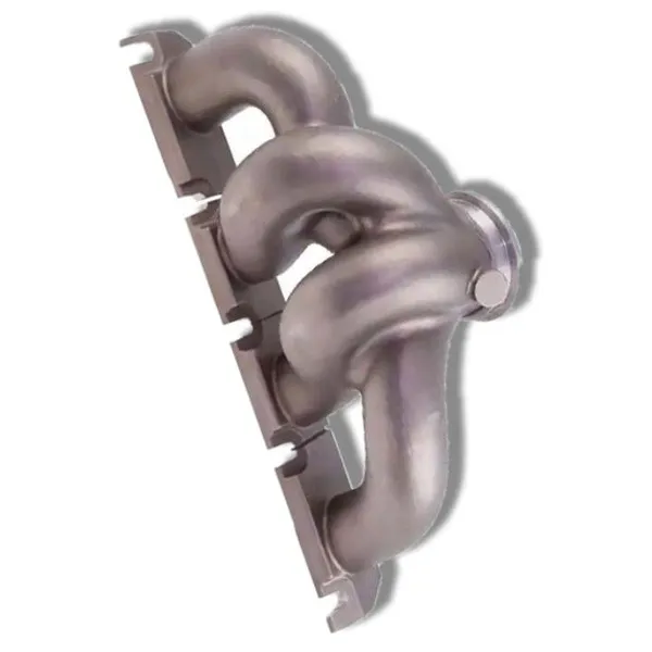 Read More
-
Live Tooling and Turn-Mill: When a Turned Part Needs Milled Features
November 18, 2026A shaft with two wrench flats and four radial holes was made in two operations for years. The lathe turned it, the mill cut the fl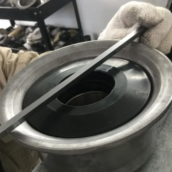 Read More
-
3-Axis vs 4-Axis vs 5-Axis Milling: What the Geometry Demands
November 17, 2026A shop quoted a housing with four angled ports on a three axis machine and won the order on price. Six weeks later the part was ru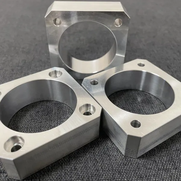 Read More
-
What Are CNC Milling Parts? Axes, Cutters and Achievable Features
November 17, 2026A bracket arrived with a 78 mm deep pocket, a 12 mm corner radius and a request for Ra 1.6 on the pocket wall. The shop quoted thr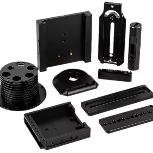 Read More

Contact Us
Recommended Products
-
 Custom CNC Machining for Aluminum and Metal Parts – OEM and ODM SolutionsNegotiableMOQ: 200 Pieces
-
CNC Machining Service for Automotive Brass Fittings With 0.8μm Surface FinishNegotiableMOQ: 500 Pieces
-
CNC Machining Service for Hydraulic System Components in Carbon SteelNegotiableMOQ: 500 Pieces
-
High-Tolerance CNC Milling Parts Titanium/Stainless Steel With Smooth Finish for Aerospace Industry ApplicationsUS$ 14MOQ: 10 Units
-
Compatible CNC Machining Service for CAD Files and Various Material TypesUS$ 12MOQ: 10 Units


-
Durable CNC Aluminum Alloy Milling Parts With Anodized Finish for Electronics and Robotics EnclosuresUS$ 12MOQ: 10 Units
-
CNC Machining Service for Industrial Robotics Aluminum Alloy PartsNegotiableMOQ: 500 Pieces
-
Professional CNC Machining Services for Aluminum, Steel, and Plastic Components With Custom SizesNegotiableMOQ: 10 Units
-
Small-Scale CNC Machining Precision Metal Parts With Tight Tolerances for RoboticsUS$ 12MOQ: 10 Units
-
5-Axis CNC Milling and Turning Services for Rapid Prototyping of Metal and Alloy PartsNegotiableMOQ: 200 Pieces


-
CNC Machining Precision Metal Parts With Fast Delivery for Prototyping and ProductionUS$ 12MOQ: 10 Units
-
Medical Grade CNC Machining Precision Metal Parts for Surgical DevicesUS$ 14MOQ: 10 Units
-
Custom CNC Machining Precision Metal Parts in Multiple Sizes and MaterialsUS$ 14MOQ: 10 Units
-
CNC Machining Service for Automotive Applications: Engine Parts and Mounting BracketsUS$ 12MOQ: 10 Units
-
Hot Selling CNC Milling Turning Customized Metal CNC Machining Services Non-standard Parts Turning Milling Composite ProcessingUS$ 10MOQ: 10 Units


-
High Grade Wholesale CNC Machining Precision Metal Parts Oem Odm Customized Aluminum Alloy Milling PartsUS$ 11MOQ: 10 Units
-
CNC Milling Parts Stainless Steel/Aluminum Alloy Compatible With CNC Machines for High-Accuracy Industrial FabricationUS$ 14MOQ: 10 Units
-
Precision CNC Milling Parts Aluminum/Steel/Brass in Various Sizes for Industrial Applications & Machinery FabricationUS$ 14MOQ: 10 Units
-
Lightweight CNC Aluminum Alloy Milling Parts Optimized for Energy-Efficient Machinery and EquipmentUS$ 12MOQ: 10 Units
-
Factory Direct Sale OEM Precision Casting Forging Service CustomizedNegotiableMOQ: 10 Pieces


