


 Business License

Reading a Casting Drawing: Draft Angles, Allowance and Datums
A bearing housing arrived at a machine shop with a drawing that held the bore to 0.03 mm and gave no datum. The shop picked the as-cast base as a reference, the casting varied 0.4 mm across ten pieces, and the first batch was scrapped for a reason that was written into the drawing rather than into the process.
Three callouts decide whether a casting drawing can be made: the draft that lets the pattern leave the sand, the allowance that lets the machinist clean up a surface, and the datum that tells everyone where the measurement starts.
The notes below explain what each callout does, how the three interact, and where a drawing usually goes wrong.
1. Casting Drawing Draft Angle: Why It Is Never Zero
A casting drawing draft angle is the taper on every face that has to leave the mould. Sand is not a rigid material, and a vertical wall dragged out of a flask will tear at the edge, so a pattern carries one to three degrees on an external face and more on an internal one.
A casting drawing draft angle of one degree is a floor rather than a target. The angle is a function of depth and of surface. A 10 mm boss needs less draft than a 100 mm wall to release the same way, and a rough sand surface needs more than a smooth one because the sand grips the pattern along its length.
Internal features need more than external ones. A core has to be withdrawn from a cavity that is surrounded by sand on all sides, so a core print at two to five degrees is normal, and a deep pocket at one degree will tear a ring of sand at the top edge on every draw.
2. Casting Machining Allowance: What the Machinist Leaves
Casting machining allowance is the extra metal on a face that will be cut. A sand casting normally carries 3 to 5 mm on a face that will be machined, and a large casting carries 6 to 10 mm because the shrinkage and the distortion grow with the size.
The allowance is not uniform and it should not be. A face that will be milled flat carries the allowance in the direction of the cut, a bore that will be bored carries it on the diameter, and a face that stays as cast carries none at all, which is why a drawing should mark which surfaces are machined rather than leaving it to a general note.
A casting machining allowance written as one note across the whole drawing applies to every face, which is rarely what the designer intended. The allowance has to survive a core shift as well. A bore cast with 4 mm of allowance and a core that moves 2 mm leaves 2 mm on one side and 6 mm on the other, and a machinist who sees 2 mm will cut it in one pass and find a hard spot or a sand inclusion under the skin.
3. Cast Part Datum Scheme: Where the Measurement Starts
A cast part datum scheme answers one question: which surfaces define the part. A casting has no precise feature to measure from, because every surface carries draft, a radius and a tolerance of its own, so the datum has to be defined deliberately rather than found in the sand.
The usual answer is a set of datum targets. Three small pads on one face locate the part in the primary direction, two on a second face locate the rotation, and one on a third locks the last degree of freedom, and those pads are cast with a local tolerance rather than the general one.
A cast part datum scheme written after the first article is a document that explains a failure rather than one that prevents it. The second answer is a machined datum. Where the part will be machined anyway, the first operation cuts a face and every later operation measures from it, which is more accurate and requires the first cut to be positioned from a cast target rather than from a guess.
4. Casting Drawing Draft Angle, Allowance and Datum Together
The three callouts interact, and a drawing that treats them separately produces a part that is expensive or impossible. A draft of three degrees on a face that will be machined is wasted, and a draft of zero on a face that will not be machined is a drawing that cannot be cast.
A casting drawing draft angle that is generous costs almost nothing in metal and saves a mould. A face at three degrees instead of one adds a few grams on a bracket and removes a torn edge that would otherwise appear on the first draw of every shift.
The interaction shows up in the allowance. A draft on a machined face adds metal at the top and removes it at the bottom, so a 4 mm allowance on a tapered wall becomes 3 mm at one edge and 5 mm at the other, and a machinist who assumes a uniform 4 mm will cut through on the thin side.
It also shows up in the datum. A datum target that sits on a drafted face is a target on a slope, and the measurement that follows carries the draft angle into the result, which is why datum pads are drawn flat and parallel rather than blended into the wall.
5. Casting Drawing Draft Angle on Internal Features
Internal draft deserves its own callout because it is the one that gets copied from an external face. A cavity formed by a core has to release in the direction the core is withdrawn, and any feature that crosses that direction becomes a loose piece or a second core.
A cross hole in a boss is the classic case. A hole that runs at right angles to the draw needs a core of its own, and a hole that runs at an angle needs either a loose piece or a design change, and the drawing should show which one is intended rather than leaving a founder to decide.
That is why a casting drawing draft angle is normally written on the core print as well as on the cavity. The radius at the bottom of a pocket belongs in the same note. A sharp internal corner traps sand and creates a hot spot, so a fillet radius of 3 to 6 mm is normal at the base of a cored pocket, and a drawing that shows a square corner is a drawing that asks for a defect.
6. Casting Machining Allowance and Distortion
Allowance has to cover distortion as well as cleanup. A long thin casting bows as it cools, and a 900 mm frame can move 2 to 3 mm out of flat, so an allowance of 4 mm on one face leaves 1 mm after a straightening that may not be possible.
Casting machining allowance is also a line on the quote. Every millimetre left on a face is metal that was melted, poured and then cut away, and a drawing that asks for 10 mm where 5 would do pays for that twice, once at the furnace and again at the spindle.
The answer is often to allow on both faces rather than one. A frame machined on both sides with 4 mm each way can be cleaned up even after a 3 mm bow, while the same frame with 4 mm on one side and none on the other has to be straightened before it can be cut.
Heat treatment belongs in the same calculation. A stress relief between roughing and finishing lets the casting move before the finish cut rather than after it, and the allowance has to be large enough to cover that movement as well as the sand tolerance.
7. Casting Drawing Draft Angle and Allowance: Callouts Compared
The table sets the three callouts against what each one instructs and the mistake that appears most often on a drawing.
| Callout | What it instructs | Common error |
|---|---|---|
| Draft on an external face | 1 to 3 degrees so the pattern releases | Draft omitted on a deep wall, sand torn at the edge |
| Draft on a core | 2 to 5 degrees, more on a deep pocket | External figure copied to an internal feature |
| Machining allowance | 3 to 5 mm small parts, 6 to 10 mm large | Single figure assumed across a tapered wall |
| As-cast face | No allowance, wider tolerance | Machined anyway, then thin at one edge |
| Datum targets | Three pads, two pads, one pad | Datum taken on a raw curved surface |
| Machined datum | First cut face defines later operations | First cut positioned from a guess |
| Fillet at a cored pocket | 3 to 6 mm at the base | Square corner drawn, hot spot cast |
8. A Case: A Cast Part Datum Scheme That Was Missing
The housing in the case at the top was a grey iron part of 12 kg with a bore of 80 mm, a machined base and two mounting pads. The drawing held the bore to the base at 0.03 mm parallel and gave no datum letter anywhere.
The shop chose the as-cast base as the primary reference and indicated it flat in a fixture. The base carried 1.5 degrees of draft and a 2 mm radius, the indicator found a different high point on every piece, and the bore ended up between 0.1 and 0.4 mm out of parallel across ten castings.
The fix was a drawing change rather than a machining change. Three datum pads were added to the base, flat and 0.05 mm above the drafted surface, and the base face was machined first from those pads and used as the datum for the bore. The scatter fell to 0.02 mm.
At Ningbo Changfeng Mechanical the drawing review checks the datum before the pattern is made, because a datum added after the tooling exists costs a pattern modification and a second first article. Changfeng Mechanical Factory issues the datum pads on the pattern drawing so the two documents cannot disagree.
9. Writing a Cast Part Datum Scheme
A cast part datum scheme that names pads rather than faces is easier to inspect. A pad can be measured with a height gauge on a plate, while a drafted curved face has no repeatable high point and the reading depends on where the probe lands.
Start from the function. The surfaces that locate the part in the assembly are the ones that should locate it in the fixture, and a drawing that datums a face nobody uses is a drawing that measures something the customer does not care about.
Put the targets on flat pads. A cast pad 8 to 12 mm across, 0.5 mm proud of the surrounding surface and marked with a local tolerance gives the machinist something to sit on, and the pad is cheap in the pattern and impossible to add later.
Separate the cast tolerance from the machined one. A general casting tolerance of a millimetre and a machined tolerance of 0.03 mm belong in two notes, and a drawing that applies the tight figure to the whole part will be quoted high and made badly.
Changfeng Mechanical Factory marks the datum targets on the pattern drawing as well as the part drawing, so the pads exist in the casting rather than in the paperwork. Ningbo Changfeng Mechanical reviews the draft and the allowance with the pattern shop in the same session, since the three figures are settled together or not at all.
10. Frequently Asked Questions on Casting Drawings
10.1 Why can a casting not have a zero draft?
Because the sand grips the pattern along the whole face and tears when the pattern is drawn. A zero draft wall releases for a few moulds if the sand is very dry and the pattern is polished, and it fails as soon as the pattern wears or the sand gets damp. One to three degrees on an external face is the practical minimum, and a deep core needs more. A casting drawing draft angle of one degree is a floor rather than a target, so treat a bigger angle as free insurance.
10.2 How much machining allowance does a sand casting need?
Three to five millimetres on a small to medium casting and six to ten on a large one, measured normal to the surface that will be cut. The figure has to cover the sand tolerance, the distortion and a core shift, so a part that will be machined on two opposite faces needs the allowance on both rather than a single larger figure on one. On a tapered wall the casting machining allowance is measured normal to the surface, which is why the figure at the top and the bottom differ.
10.3 What is the difference between a cast datum and a machined datum?
A cast datum is a set of pads formed in the mould and used to position the first cut, and a machined datum is a face produced by that cut and used for everything after it. A drawing normally needs both, since the first operation has to start somewhere and every later operation needs a surface that is flat and parallel. A cast part datum scheme that mixes the two in one note is the source of most first article arguments.
10.4 Can a casting drawing hold a tolerance of 0.05 mm?
It can hold it on a machined feature and not on an as-cast one. A sand casting in a normal grade varies by a millimetre or more across a large dimension, so an as-cast tolerance of 0.05 mm is a request the process cannot answer. Mark the tight features as machined and leave the rest to the casting grade. A drawing that applies 0.05 mm to the whole part will be quoted high, made badly and rejected on a feature nobody uses.
Recently Posted
-
What Are Casting Parts? Sand, Investment and Die Cast Routes
November 16, 2026A casting is a part shaped by pouring liquid metal into a cavity. Three routes do that in three different ways: green sand uses a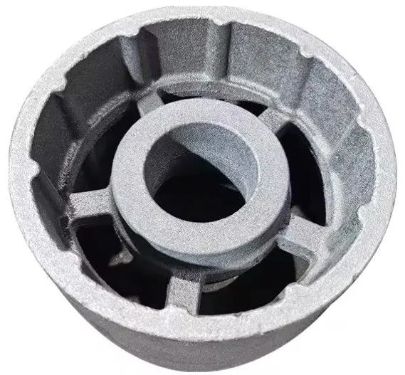 Read More
-
Brass Parts Surface Finishing: From As-Machined to Nickel Plated
November 16, 2026A box of brass fittings arrived with a finish the buyer had not asked for and did not want. Half the parts were bright and half we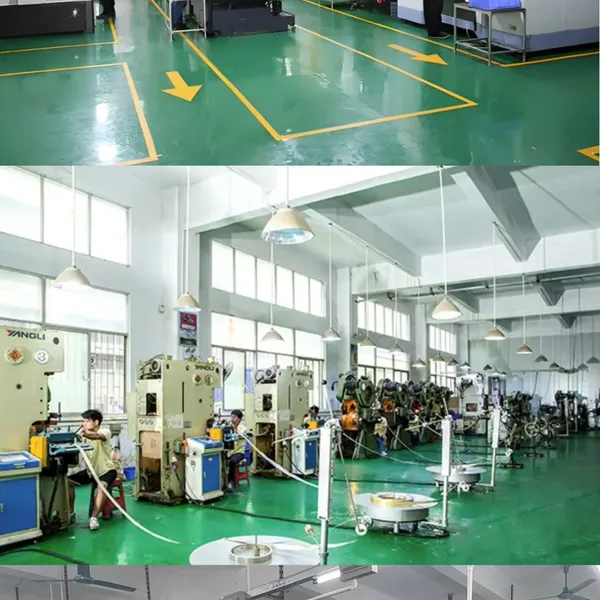 Read More
-
What Are Brass Parts? Alloy Families and Machined Component Basics
November 16, 2026A shipment of 2,400 machined brass fittings reached a customer in northern Europe and came back six weeks later with a 3 percent l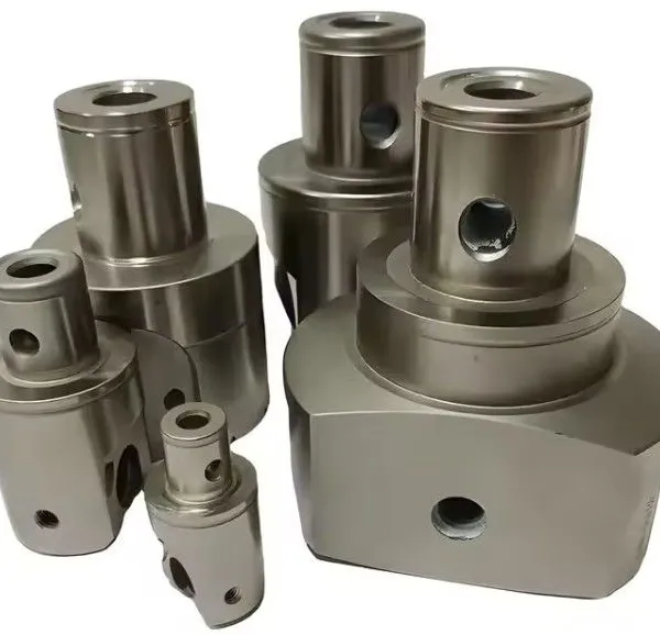 Read More

Contact Us
Recommended Products
-
 Custom CNC Machining for Aluminum and Metal Parts – OEM and ODM SolutionsNegotiableMOQ: 200 Pieces
-
CNC Machining Service for Automotive Brass Fittings With 0.8μm Surface FinishNegotiableMOQ: 500 Pieces
-
CNC Machining Service for Hydraulic System Components in Carbon SteelNegotiableMOQ: 500 Pieces
-
High-Tolerance CNC Milling Parts Titanium/Stainless Steel With Smooth Finish for Aerospace Industry ApplicationsUS$ 14MOQ: 10 Units
-
Compatible CNC Machining Service for CAD Files and Various Material TypesUS$ 12MOQ: 10 Units


-
Durable CNC Aluminum Alloy Milling Parts With Anodized Finish for Electronics and Robotics EnclosuresUS$ 12MOQ: 10 Units
-
CNC Machining Service for Industrial Robotics Aluminum Alloy PartsNegotiableMOQ: 500 Pieces
-
Professional CNC Machining Services for Aluminum, Steel, and Plastic Components With Custom SizesNegotiableMOQ: 10 Units
-
Small-Scale CNC Machining Precision Metal Parts With Tight Tolerances for RoboticsUS$ 12MOQ: 10 Units
-
5-Axis CNC Milling and Turning Services for Rapid Prototyping of Metal and Alloy PartsNegotiableMOQ: 200 Pieces


-
CNC Machining Precision Metal Parts With Fast Delivery for Prototyping and ProductionUS$ 12MOQ: 10 Units
-
Medical Grade CNC Machining Precision Metal Parts for Surgical DevicesUS$ 14MOQ: 10 Units
-
Custom CNC Machining Precision Metal Parts in Multiple Sizes and MaterialsUS$ 14MOQ: 10 Units
-
CNC Machining Service for Automotive Applications: Engine Parts and Mounting BracketsUS$ 12MOQ: 10 Units
-
Hot Selling CNC Milling Turning Customized Metal CNC Machining Services Non-standard Parts Turning Milling Composite ProcessingUS$ 10MOQ: 10 Units


-
High Grade Wholesale CNC Machining Precision Metal Parts Oem Odm Customized Aluminum Alloy Milling PartsUS$ 11MOQ: 10 Units
-
CNC Milling Parts Stainless Steel/Aluminum Alloy Compatible With CNC Machines for High-Accuracy Industrial FabricationUS$ 14MOQ: 10 Units
-
Precision CNC Milling Parts Aluminum/Steel/Brass in Various Sizes for Industrial Applications & Machinery FabricationUS$ 14MOQ: 10 Units
-
Lightweight CNC Aluminum Alloy Milling Parts Optimized for Energy-Efficient Machinery and EquipmentUS$ 12MOQ: 10 Units
-
Factory Direct Sale OEM Precision Casting Forging Service CustomizedNegotiableMOQ: 10 Pieces


